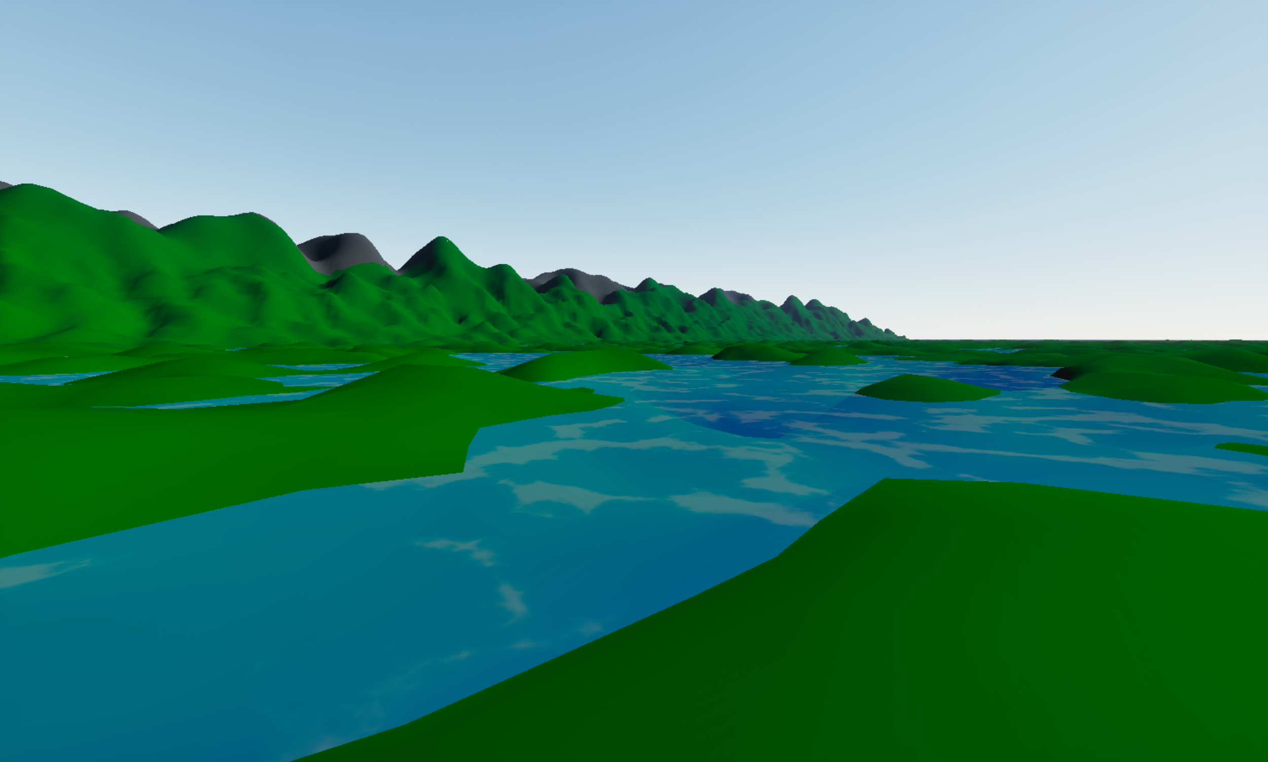
Valheim Style Procedural Terrain
In this post, I will explain the process I used to procedurally generate terrain for a ring world similar to the approach used by Valheim.
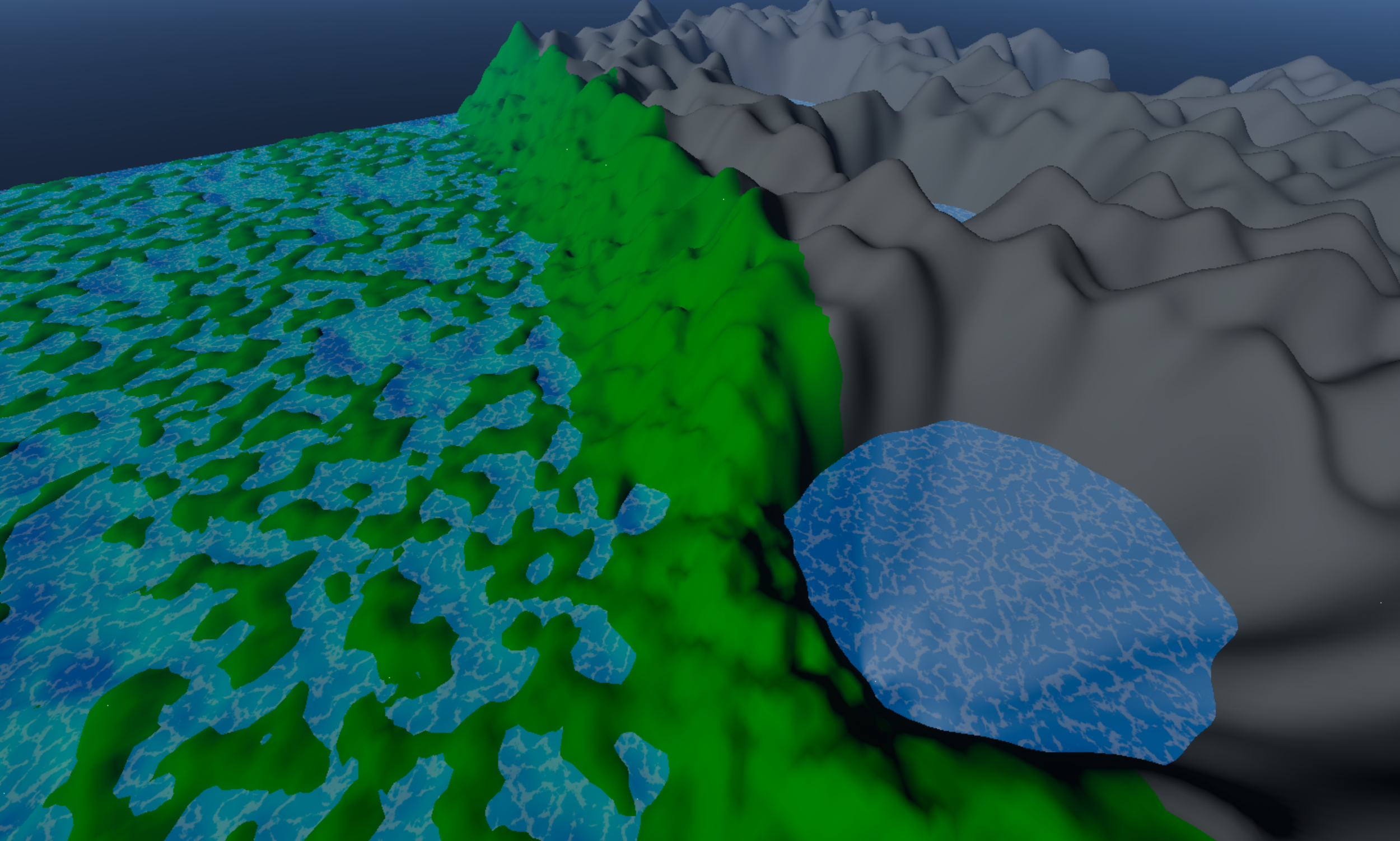
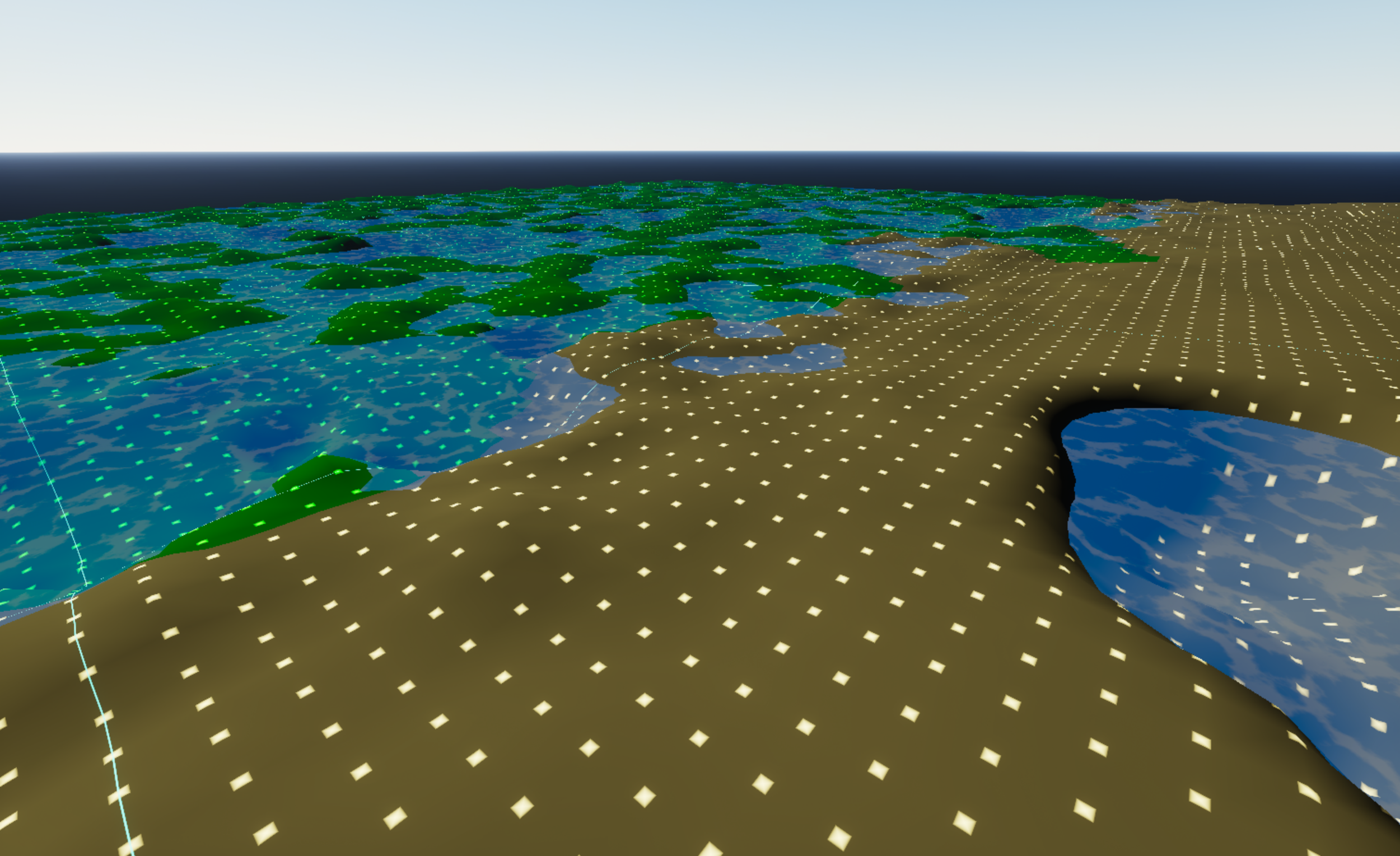
The system was built in Unreal Engine 5.7 using C++ and Blueprints. It allows for the definition of multiple biomes with a series of parameters that define how the terrain will be generated for that biome. There is also a debug material that displays the position of each vertex that was generated for the terrain. It also displays blue lines to highlight the seams between each sector of the terrain.
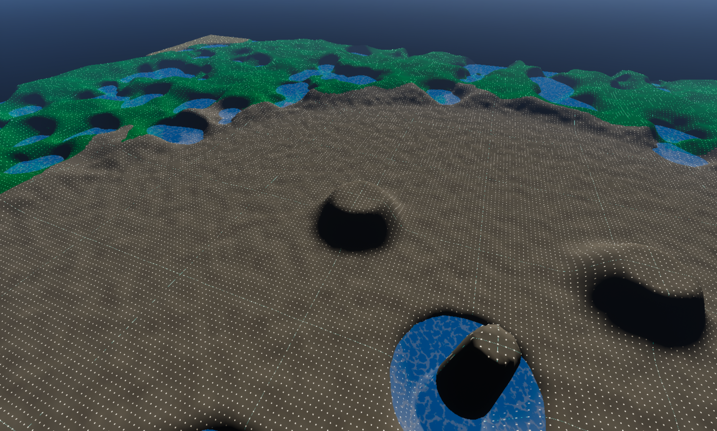
I have also designed a series of “brushes” that can be used to modify the terrain by raising it up or down or smoothing out the surface. These brushes are currently usable through code, but they will eventually be extended to gameplay use as well.
The primary element used to build the terrain is the Procedural Mesh Component. The world is separated into sectors, and each sector is rendered using one of these components when the player is close enough to view it.
This component allows you to define a series of vertices that can be gathered together into a mesh. In my design, there is a small pool of these components generated on startup, and then the mesh data is updated to match the sectors that currently surround the player.
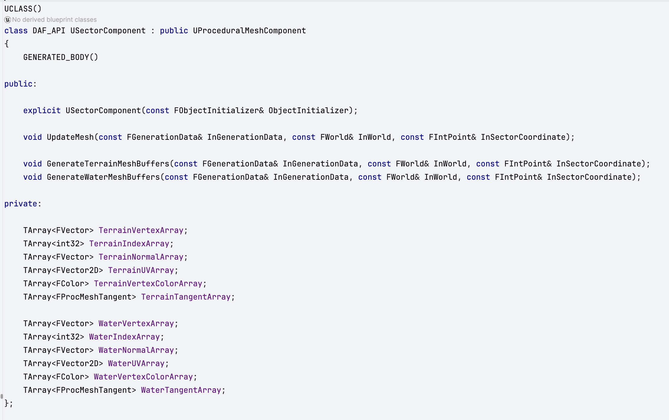
All of the world data is generated initially, and then only referenced by the Sector component when it is required. Much of the generation is customizable using an Unreal data asset that is available to designers in the editor.
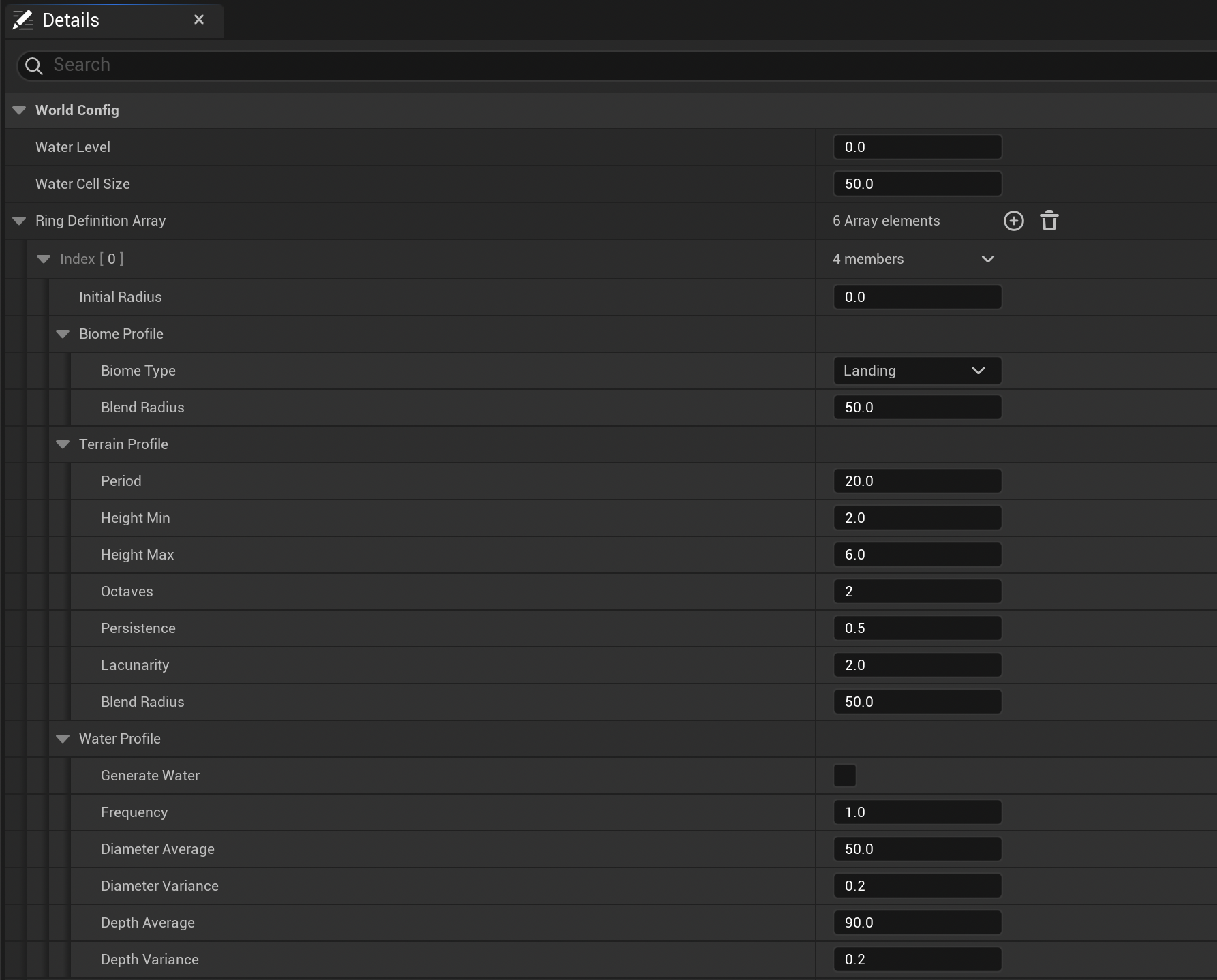
This asset allows biomes to be defined using a series of parameters related to the generation of terrain and water. The biome types are defined within the C++.
Ring Generation
There are series of techniques used to generate the individual rings and ensure the biomes blend together well.
This requires a custom shader so that the material can recognize how to color each vertex according to its biome stats. In order to do this, an index into the Biome Type enum is passed into the shader using the Red channel of the Vertex color. This way each vertex in the shader can recover its Biome Type during rendering.
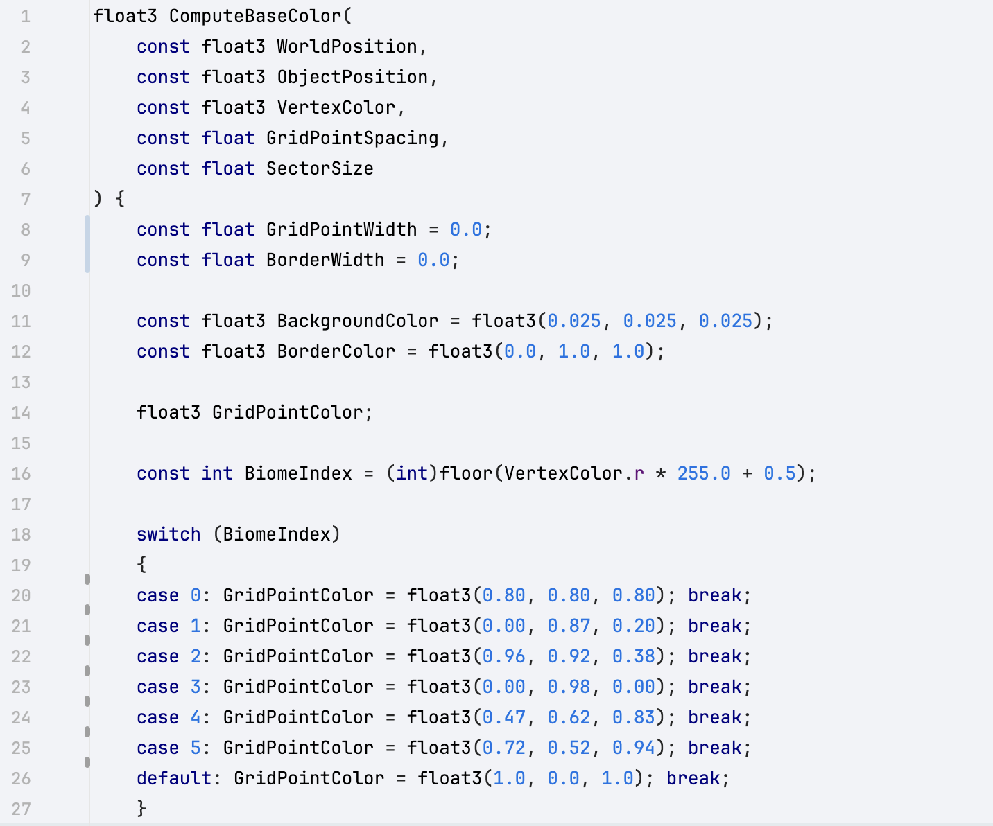
This also requires the Biome Index to be packed into the range between 0.0f and 1.0f so that it can be passed as a the Red value, and then it must be unpacked in the shader.
On line 16 in the previous code example, you can see the unpacking process.
The Biome Index is initially passed to the shader during the Sector Component updating process. This is where I define the position, normal, etc. for all of the Sector vertices, and I also prepare the Biome Index and place it into the red channel.
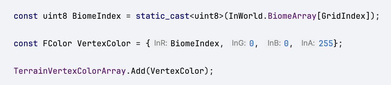
You can see here why the information needs to be packed. The FColor struct that carries the vertex color information uses 8 bit integers to store the color information, but these will be converted into floats when they are passed through to the shader. In order, to recover the original integer index it requires us to reverse that process.
The custom shader is included in the Material Graph. Notice for this process to work the node also requires a few constants related to the size of the world to be passed in as inputs.
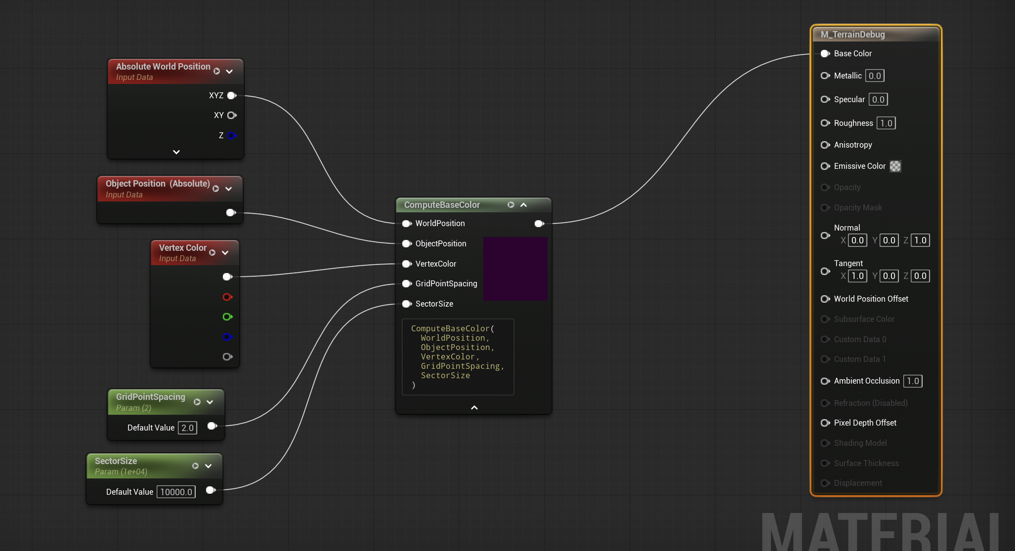
The actual organization of the biomes into rings is relatively easy. It simply requires each vertex to check how far it is out from the center of the world in order to decide what Biome region it sits in. Once a vertex knows which biome it exists in then it can be textured correctly.
There is also a bit of noise added to the edges of each ring in order to create a blending effect so that the biomes do not change abruptly. Notice this blending between the biomes is also customizable for each Biome transition using the Blend Radius parameter in the data asset.
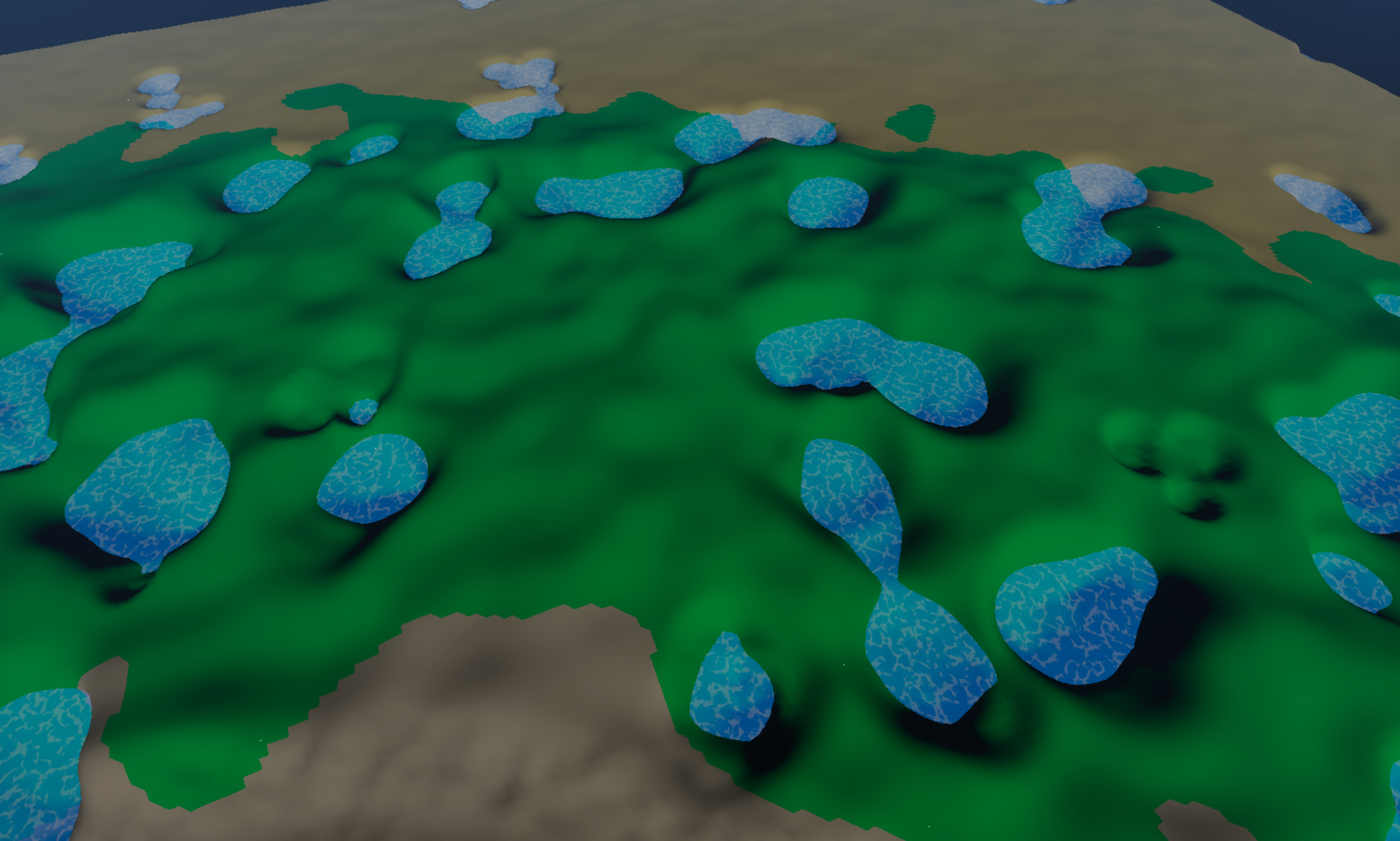
The scale of the terrain can sometimes be hard to recognize when flying far above the land, but each vertex in the world is actually 4.0 meters apart in Unreal units.
So when walking along the ground, the features are quite large. The test world is 5000.0 meters in radius.